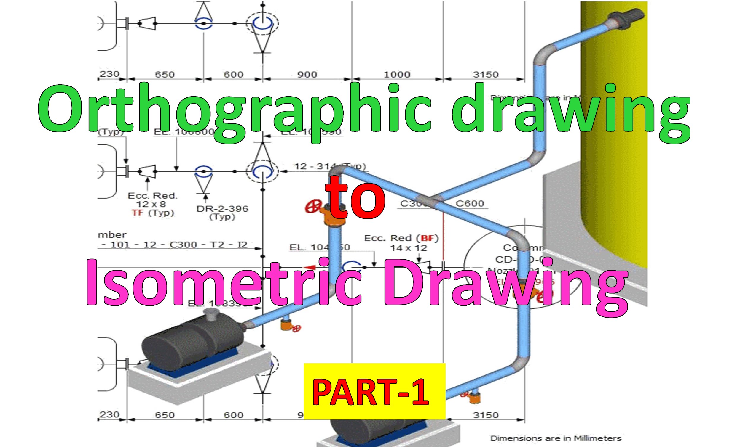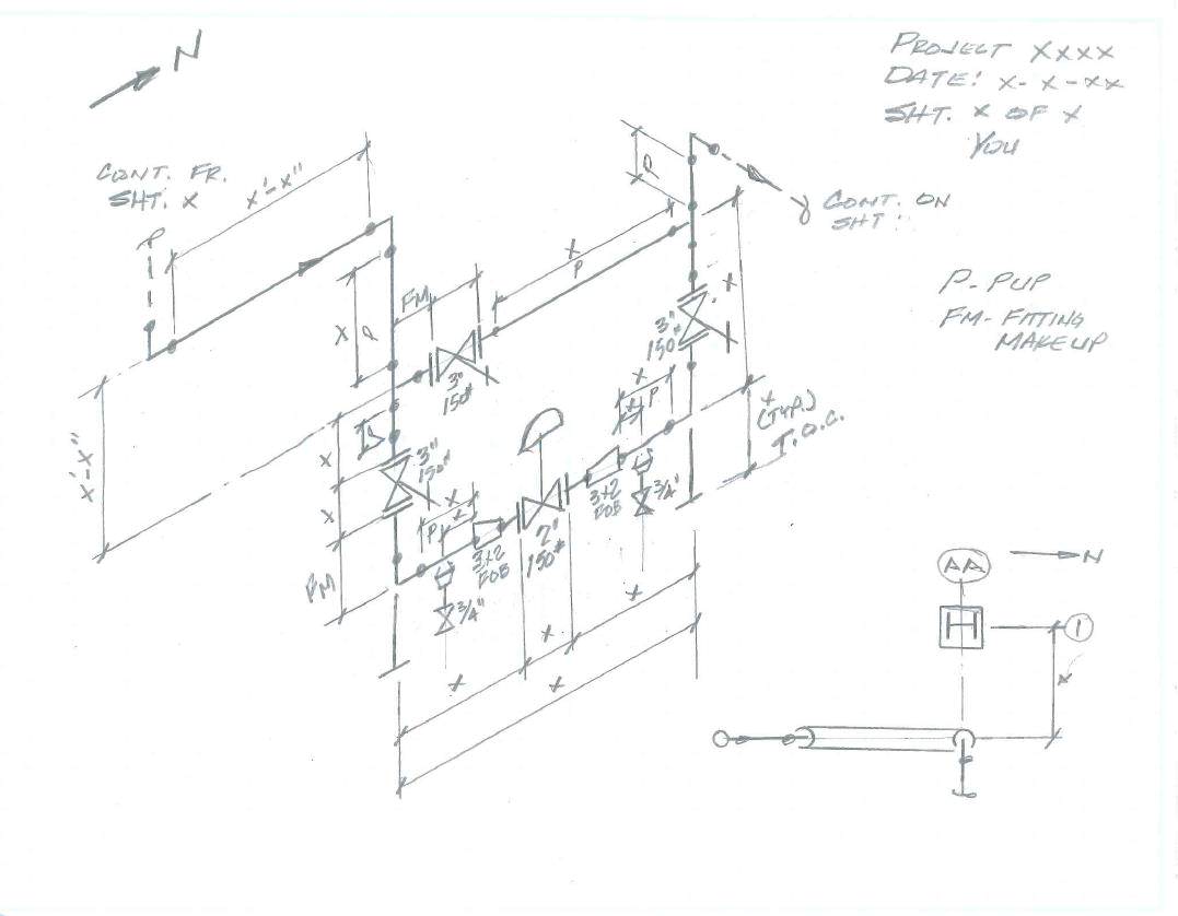

Here, piping isometric sketching plays an essential function. So that students can comprehend fully and develop a vision of how spools are constructed and how a pipe is connected to other pieces of machinery or unique objects. The execution person must have access to all the necessary information. To execute a piping project, either in the yard for fabrication or in the field for erection and construction, piping designers must convey the same information to the person carrying out that piping work after creating a 3-D model in PDMS, SP3D, or any other program. Pythagoras Theorem (For Rolling movement of Pipe).You need to be aware of these four crucial concepts to comprehend any Piping isometric drawing: From becoming aware of an isometric piping drawing to learning how to read it correctly. Here, we’ll concentrate on becoming acquainted with piping isometrics. Outlet bolts and gaskets in which line, inlet or outlet.In our previous article on What Is Piping, we gave you a synopsis of Piping Isometric Drawings.Some of these requirements can be regarding following points These needs to be reflected in isometrics drawings. Project Specific Instructions for Isometrics CheckingĮvery project has specific requirements. Piping Isometric Drawing Checklist Isometric Drawing Symbols It includes General Isomtric Check Points as well as Project Specific Check Points. Isometric drawing needs to be checked as per project standard isometric drawing checklist. Inch Dia = Pipe size in Inch X Number of Joints Isometric Drawing Checklist Inch Meter = Pipe length in Meters X Pipe Size in Inch Pipe line details such as Line Number, Line Size, Insulation, Tracing, Fluid Code, Operating and Design pressure and temperatures, Pressure Testing method such as hydrotest or pneumatic, Test pressure, Piping material class, Inch Dia etc.Project details such as client name, engineering office name, project name, project number, process licensor etc.Title bar section at the bottom consists of following information. Whether shop material or field material.It includes following information for all components : Section on left or right side of drawing consists of B ill of Material Section for the portion of line shown in isometric graphic.


Main Graphic section consist of Isometric Representation of a pipe line route in 3D space, which includes following information : Piping isometric drawing consists of three sections. Piping fabrication work is based on isometric drawings. It is the most important deliverable of piping engineering department. Piping Isometric drawing is an isometric representation of single pipe line in a plant.


 0 kommentar(er)
